When dealing with mesh—especially outdoor and long-distance deployments—precision is your only safeguard against failure. Every mistake has a high cost: if you configure a Root Access Point (RAP) incorrectly while it’s mounted 50 feet in the air, you face the miserable task of unmounting it in bad weather just to fix a basic setting. Plan ahead, verify on the ground, and respect the physics of RF.
1. Strategic Channel Selection for the RAP
The Root Access Point (RAP) dictates the health of the entire mesh tree. While Mesh Points (MAPs) should generally be left to auto-detect and scan all channels to find their parent, the RAP requires manual precision.
Manual Override: Manually select the optimal channel and set the Transmit Power Control (TPC) to a fixed level (typically Level 1 for max power) to ensure the highest possible Signal-to-Noise Ratio (SNR) over long distances.
Regional Best Practices:
In the US (FCC):
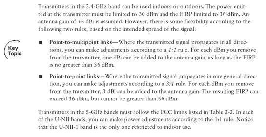
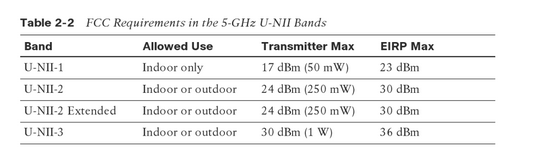
Utilize UNII-3 channels as they are the standard for outdoor backhaul with higher power limits.
2.4 GHz P2P Links: You can utilize the 3:1 rule; for every 3 dBi of antenna gain added, the transmitter power must be reduced by 1 dBm. The maximum transmitter power is 30 dBm, but the resulting EIRP can exceed 36 dBm, capped at a maximum of 56 dBm.
5 GHz Links: These follow the 1:1 rule, where the maximum EIRP is restricted to the specific limits defined in the regulatory tables (e.g., 36 dBm for UNII-3).
In Europe (ETSI):
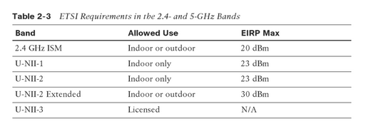
Your best outdoor option is typically UNII-2 Extended, as UNII-1 and UNII-2 are restricted to indoor use.
Regulatory Rules: Both 2.4 GHz and 5 GHz bands follow the 1:1 rule. Always check local laws as regulations may differ significantly by country.
Understanding the EIRP Formula
To stay within legal limits while maximizing range, you must calculate your Effective Isotropic Radiated Power (EIRP) correctly:
The DFS Trap: Why Static Channels Matter
Avoid using UNII-2 Extended (DFS) channels for static mesh backhaul if possible.
The Problem: If a static RAP detects radar on a DFS channel, it will shut down the radio and will not turn back on until the radar is gone or the AP is moved. Because the channel is hardcoded (static), the AP cannot move to a different channel automatically; an engineer must manually update it.
The Workaround: Instead of a single static channel, build a Custom RF Profile to give the RAP a “safe” list of channels to choose from:
In the US (FCC): Build the profile containing only UNII-3 channels to completely avoid DFS-sensitive bands.
In Europe (ETSI): Since options are more limited, set the RF profile with UNII-2 Extended and include UNII-1 as a fallback option.
The Result: This allows the RAP to choose the best environment-dependent channel while staying away from (or having a recovery path for) DFS-sensitive bands.
Stabilizing the Link: DCA Intervals
Frequent channel changes are the enemy of mesh stability.
DCA Interval: Set your Dynamic Channel Assignment (DCA) interval between 12 and 24 hours.
The Logic: You want to minimize frequency shifts; otherwise, the Mesh bridging will “flap”. If the RAP changes channels, the entire mesh tree is disrupted as MAPs must re-scan to find their parent.
Mandatory Behavior: Note that if a DFS beacon is received by the AP, it will immediately trigger a new RRM DCA channel reassignment regardless of your interval settings. This behavior is hardcoded for regulatory compliance and cannot be updated.
2. Why Wide Channels Kill Long-Distance Mesh
When designing outdoor mesh, especially for distance, avoid 40 MHz, 80 MHz, or 160 MHz channel widths. While bonding channels increases bandwidth, it also significantly increases the noise floor, which directly decreases your Signal-to-Noise Ratio (SNR).
The Physics of Noise Floor vs. Bandwidth
Every time you double your channel width, you introduce more noise into the receiver:
40 MHz: Increases noise by 3 dBm.
80 MHz: Increases noise by 6 dBm.
160 MHz: Increases noise by 9 dBm.
Pro Tip on Decibels: Remember that a 3 dB increase represents a doubling of signal strength; a 6 dB increase means the signal (or in this case, the noise) has doubled twice.
SNR and Link Stability
A higher noise floor combined with lower RSSI results in a low SNR. This forces the AP radio to shift down to lower MCS rates (lower modulation data rates).
Minimum SNR for Mesh: You should aim for a minimum SNR of 20 to maintain a stable link.
The Danger Zone: Anything below an SNR of 15 is considered unstable. If your AP is already at its lowest data rate and the SNR drops further, the link will fail entirely.
Channel Availability and Interference
Wide channels significantly increase the probability of interference, especially across long distances where other wireless networks might reside between your APs.
The UNII-3 Constraint: In the UNII-3 band, there are only 5 free channels.
Using 80 MHz consumes almost the entire band (only 1 option).
Using 40 MHz gives you only 2 options.
Using 20 MHz gives you 5 distinct options.
The Trade-off: If you encounter interference on a wide channel, you are often forced to move to UNII-2 or UNII-2 Extended. This results in a downsized EIRP, which directly reduces your maximum range. By sticking to 20 MHz, you retain the flexibility to hop to a clean channel while staying within the UNII-3 range for maximum allowed EIRP under FCC regulations.
3. Why Antenna Gain Matters: The “Flashlight” Principle
Choosing the proper antenna for the job is non-negotiable because antenna gain determines focus.
Think of it like a flashlight:
Unfocused Light: If you have a 30W bulb but the light is not focused, it spreads everywhere and doesn’t travel very far.
Focused Beam: If you focus that same 30W into a small area or a single direction, the light travels much further.
Laser Focus: If you focus it enough to become a laser beam, it reaches incredible distances because the same amount of power is concentrated into a tiny point.
The same principle applies to radio waves. By forcing the RF energy into a smaller area, the “force” or intensity of the signal increases in that specific direction.
Omnidirectional Antennas and the “Squished Donut”
Low/No Gain: An omni-directional antenna with no gain provides 360∘ coverage but has no focus. Its radiation pattern is like a large, round donut—equal height and width.
High Gain (e.g., 6 dBi): As you increase the gain on an omni antenna, that “donut” becomes squished. Because the same power must go somewhere, it is pushed outward horizontally. This increases your 360∘ range at the expense of vertical coverage.
Directional Antennas: Patch vs. Dish
For Mesh backhaul and long-distance Point-to-Point (P2P) links, directional antennas are essential:
Dish Antennas: These typically have locked gains due to their physical design (parabolic shape). They act like the “laser beam” of the RF world, providing the most focus for the longest distances.
Patch Antennas: These provide a wide beam in one direction. In some software-defined systems, you must manually configure the antenna gain in the controller to ensure the EIRP calculations are accurate.
The Bottom Line: Selecting the right antenna and gain allows you to focus radio waves in the desired direction. This results in better RSSI and SNR, which are the foundations of a stable, high-performance link over long distances.
4. Precision Alignment: Azimuth, Elevation, and Tilt
When deploying outdoor mesh, physical orientation is everything. You must ensure that antennas are pointed accurately toward the next hop in your mesh tree.
Understanding Antenna Patterns
Every antenna has a specific “fingerprint” known as an antenna pattern, which consists of two main planes:
Azimuth Plane: The horizontal spread of the signal (left to right).
Elevation Plane: The vertical spread of the signal (up and down).
If the antenna is mounted incorrectly, the AP will transmit the radio energy in the wrong direction, causing the Root Access Point (RAP) or Mesh Access Point (MAP) to miss the signal entirely. This rule of precise alignment applies to both ends of the link.
The Height Trap: Tilt and the “Donut” Shape
Even with omnidirectional antennas, placement is not “set it and forget it.” While an omni-directional signal leaves the antenna in a donut shape, it still has limited vertical coverage.
The Scenario: Imagine your RAP is mounted 15 feet high on a pole, but your MAP is 45 feet high on a different building.
The Risk: Without proper mechanical tilt, the MAP may sit “above” the RAP’s signal donut.
The Fix: You must tilt the antennas at the correct angle so they are pointing directly toward one another. Without this vertical adjustment, the devices may be “deaf” to each other despite being in relatively close proximity.
The Bottom Line: Never assume “line of sight” is enough. You must align the centers of your antenna patterns horizontally and vertically to ensure maximum signal transfer and link stability.
5. Line of Sight is Not Enough: The Fresnel Zone
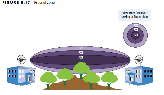
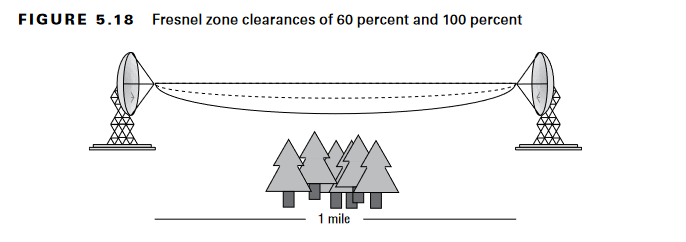
In outdoor mesh and bridging, a clear visual line of sight between the RAP and MAP does not guarantee a healthy link. You must also ensure the Fresnel Zone—an elliptical area around the direct visual path—is clear of obstructions.
The 60% Rule
Radio waves do not travel in a straight “laser” line; they spread out. Under no circumstances should you allow objects like trees or buildings to encroach more than 40% into the first Fresnel zone.
The Goal: Aim for 100% clearance.
The Minimum: You must maintain at least 60% clearance to keep the communication link reliable. Encroachment beyond 40% (leaving less than 60% open) will likely cause significant performance degradation or total link failure.
Calculating the Fresnel Zone Radius
To determine if an obstacle is a threat, you need to calculate the radius of the zone at that specific point.
For the Total Radius (100%) at the midpoint of the link:

To calculate the 60% Clearance Radius (the absolute minimum space needed):

Real-World Example: The “Tree” Problem
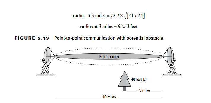
Imagine a 10-mile P2P link (2.4 GHz) with a 40-foot tree located 3 miles away from one antenna:
Calculate the radius at that 3-mile point: Using the specific point formula, the radius is approximately 67.53 feet.
Determine Antenna Height:
To have 100% clearance, the antennas must be mounted at least 108 feet high (40 ft tree+67.53 ft radius).
To maintain the minimum 60% clearance, you need at least 40.52 feet of space above the tree (60% of 67.53 ft). This means your antennas must be at least 81 feet high.
The “Living” Obstacle Warning
Always account for the future. Trees grow. What is a “clean” 60% clearance today might become a 50% obstruction in two years. Periodically check your long-distance links to ensure that new construction or growing foliage hasn’t encroached into your signal path.
Pro-Tip: As links get longer (over 7 miles), you must also begin to calculate for the Earth’s Bulge, which can effectively “lift” the ground into your Fresnel zone.
6. Calculations: Predicting Mesh Distance
Calculating distance isn’t just about the hardware vendor; it depends entirely on the antenna characteristics and how they are configured.
The EIRP Formula Revisited
To understand your link’s potential, you must first calculate the Effective Isotropic Radiated Power (EIRP):
Consider two scenarios that result in nearly the same EIRP but behave very differently in the field:
Scenario 1 (High Power, Low Gain): 25 dBm (Tx) − 1 dB (Cable) + 6 dBi (Antenna) = 30 dBm EIRP.
Scenario 2 (Lower Power, High Gain): 16 dBm (Tx) − 1 dB (Cable) + 14 dBi (Antenna) = 29 dBm EIRP.
Which is better? While the total power is almost identical, Scenario 2 is superior for Point-to-Point (P2P) links. High antenna gain focuses the raw power into a narrow beam rather than letting it “spray” everywhere. This makes you a “good neighbor” by reducing interference for surrounding networks while pushing your signal further.
Free Path Loss: The “Air” Tax
In the real world, signal strength is lost as it travels through air, dust, and moisture. This is known as Free Path Loss (FPL).
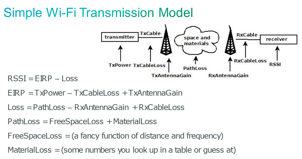
To calculate what the signal strength will be at the receiving end (RSSI), we use the transmission model shown in image below:
How Antenna Gain Fights Path Loss
Look at how increasing antenna gain dramatically improves the RSSI at a fixed distance of 300 feet (at 5745 MHz / Channel 149):
0 dBi Gain: 36 dBm EIRP− 86.85 dB Path Loss = −50.85 dBm
4 dBi Gain: 36 dBm EIRP − 78.85 dB Path Loss = −42.85 dBm
6 dBi Gain: 36 dBm EIRP−74.85 dB Path Loss = −38.85 dBm
14 dBi Gain: 36 dBm EIRP−58.85 dB Path Loss = −22.85 dBm
Just like a water hose with a smaller opening, a focused beam travels further and is less affected by the “drag” of Free Path Loss.
Real-World Range Expectations
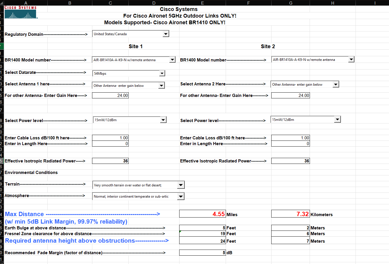
When you avoid channel bonding and focus your energy, every dBm counts. Using professional calculation tools (like the legacy Cisco Outdoor Bridge Tool), we can see how gain changes the “reach” of a link at a constant 36 dBm EIRP:
Low Gain Setup: 22 dBm Tx+14 dBi Gain
Max Distance: ~1.4 miles (2.3 km)
Fresnel Clearance Required: 11 feet (3 meters)
High Gain Setup: 12 dBm Tx+24 dBi Gain
Max Distance: ~4.5 miles (7.3 km)
Fresnel Clearance Required: 19 feet (6 meters)
The takeaway: Higher gain doesn’t just give you a better signal; it exponentially increases your stable distance while requiring much lower transmit power from the AP itself.
Regulatory Compliance and Cisco Safety Rails
When designing for peak performance, you must always operate within FCC or ETSI regulations. Exceeding the maximum allowed EIRP is not only poor engineering—it is illegal.
Software Locks: To prevent accidental violations, Cisco hardcodes regulatory limits into the software of all indoor and current outdoor Access Points.
Automatic Adjustment: If you manually increase the Antenna Gain setting in the controller, Cisco software will automatically lower the TxPower to ensure the total EIRP does not exceed legal limits.
Licensed Operation: If your specific deployment requires you to exceed standard EIRP limits using high-gain antennas and maximum transmit power, you must utilize specific hardware and possess the appropriate regulatory license to operate on those channels legally.
The “Weather Margin”: Planning for Reality
A link that is “just enough” during a clear sunny day will likely fail when the seasons change. High-performance mesh requires an SNR margin to account for atmospheric variables.
Free Path Loss vs. Weather: Rain, snow, and even high humidity introduce particles into the air that absorb or scatter radio waves.
Signal Degradation: These particles increase the total path loss, damaging the signal quality and reducing your SNR.
The Golden Rule of Stability: Always build a buffer into your SNR targets. A healthy margin ensures that when the weather turns, your link remains stable and the link you’ve built holds up under pressure.
Summary:
By selecting the right hardware, respecting the laws of physics (Fresnel zones and EIRP), and accounting for the environment, you transform a risky outdoor deployment into a professional-grade backhaul.
External References & Tools
For those who want to dive even deeper into the physics or need to run their own precise calculations, I recommend these essential resources:
Cisco 9800 Wireless RF Reference Guide – The definitive source for how Cisco handles RF, RRM, and regulatory domains.
Antenna-Theory.com – A fantastic resource for understanding the complex physics of azimuth, elevation, and gain.
Pasternack FSPL Calculator – My go-to tool for calculating Free Space Path Loss to predict link viability.